How to Make a Custom Tool Insert from a Photo for 3D Printing
A practical workflow from photo and scale to a checked 3D preview and 3MF, STL, DXF or SVG export
To make a custom tool insert from a photo, you do not have to trace every object or build every pocket by hand in CAD. AIPRINTGEN detects the visible outlines, converts pixels to real dimensions and creates an insert for a drawer, tool case, product box or workstation.
Create a fitted insert from a photo without modeling it from scratch in CAD
Upload a photo, set the scale, check the outlines and download 3MF, STL, DXF or SVG.
Photo → scale → outlines → ready 3D model
Open the Custom Insert Generator →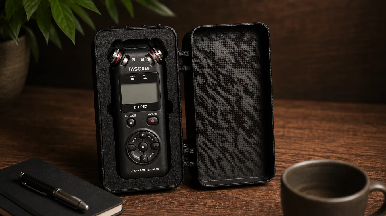
What is a custom tool insert?
A custom insert is a tray or liner with one or more pockets shaped for specific objects. Depending on the application, it may be called a tool insert, drawer organizer, case insert, packaging insert or fitted tray.
Because every pocket follows its assigned object, the insert keeps a set in a predictable position and makes a missing tool easy to spot.
Typical uses include:
- tool drawers and workshop carts;
- hard cases and protective cases;
- product boxes and presentation packaging;
- measuring instruments and electronics;
- service kits, demonstration sets and production tooling.
What the AIPRINTGEN Custom Insert Generator creates
The generator builds a plate with pockets based on the outlines you have reviewed. You can make a free-size insert for a box, drawer or case, or choose a modular Gridfinity organizer.
In the browser, you can:
- upload one or several objects in the same photo;
- set the real scale in millimeters;
- correct automatically detected outlines;
- add a missed object or an internal cutout;
- adjust pocket depth and object clearance;
- add finger notches;
- move and resize individual pockets;
- enter exact overall plate dimensions;
- inspect the result in an interactive 3D preview;
- download a file for the chosen manufacturing workflow.
The workflow runs in the browser, so a separate CAD application is not required for a basic constant-depth insert.
How to photograph tools for an accurate insert
Photo quality directly affects how cleanly the object boundaries can be detected. You do not need studio equipment, but the top view should be unambiguous.
Before taking the picture:
- place all objects flat on one level surface;
- make sure no objects overlap;
- use a background that contrasts with the objects;
- leave clear space between neighboring objects;
- hold the camera parallel to the surface;
- avoid hard shadows, glare and strong perspective distortion.
For automatic scaling, place the objects on a complete A4 sheet. Because the sheet dimensions are known, the generator can convert the image from pixels to millimeters.
An A4 sheet is optional. If it does not fit or its edges are not detected reliably, choose the known-distance mode, mark two points and enter the real distance between them—for example, part of a ruler or a measured span on a caliper.
Accepted uploads are JPG, PNG, WebP and HEIC files up to 20 MB.

How to make a custom tool insert from a photo
Step 1: Upload the photo and set the scale
Open the generator, select your photo and choose how the real dimensions should be established:
- from a complete A4 sheet—automatically;
- from a known distance—manually with two points.
For manual calibration, place the two markers at the ends of a segment you have measured and enter that distance in millimeters.
Before editing outlines, compare one calculated object dimension with a real measurement. Any scale error affects the entire tray, case insert or packaging insert.
Step 2: Review the detected objects
The generator separates visible areas into object outlines. Zoom in and check every boundary before building the model.
The outline editor lets you:
- remove a false detection;
- draw an object that was missed;
- add an internal cutout;
- change the detail level of the selected outline;
- move individual contour points.
The detail slider ranges from a simplified outline to one that retains more nodes. Straight sections rarely need maximum detail, while handles, projections and tight curves may benefit from extra points.
To add a missed object manually, mark its boundary in sequence. The interface recommends roughly 6–12 points for the initial outline, which you can refine afterward.


Step 3: Choose the insert type and dimensions
For a conventional tool tray, case insert or packaging liner, choose the free-size packaging insert. Despite the label, this plate also works for drawers, workshop carts and protective cases.
The main settings are:
| Setting | What it controls |
|---|---|
| Pocket depth | How far the object sits below the top of the insert. |
| Object fit | The manufacturing clearance between the object and the pocket wall. |
| Finger notches | Extra access areas that make the object easier to lift out. |
| Outer margin | The distance from the pockets to the edge of the plate. |
| Bottom thickness | The amount of material below the lowest point of a pocket. |
| Plate corner radius | Rounding for the outside corners of the insert. |
| Fixed plate size | An exact width and length for the completed plate. |
Pocket depth can be set from 1 to 150 mm. Available fit clearances are 0.4, 0.8 and 1.2 mm. A smaller value gives a tighter nominal fit; a larger value leaves more room around the object.
Step 4: Arrange the pockets
After the outlines are confirmed, the layout editor lets you position the pockets relative to one another and to the edge of the insert.
Drag the center of a pocket to move it. The square corner handles change its size. Resize with care: if the photo scale is already correct, scaling the pocket also changes its real-world fit.
The round handles represent finger notches. Move them around each pocket to a convenient pickup point, while preserving enough material in narrow webs between neighboring recesses.

Step 5: Set the finished insert size
By default, the plate size follows the pocket layout and outer margin. If the insert must fit an existing drawer, case or box, enable the fixed blank size option.
Enter the plate width and length in millimeters. The generator supports a maximum plate side of 1200 mm.
Whether the insert can be manufactured in one piece depends on the build area of your 3D printer, router or laser. If it is larger than the available work area, prepare the split and joints separately.

Step 6: Build and inspect the 3D model
Select “Build the 3D model” to open the finished preview. It shows the interactive model, overall dimensions, pocket count, mesh-closure status and export format choices.
Rotate and zoom the model to inspect it from several angles. Confirm that the bottom is continuous, no pocket crosses the plate edge and the webs between pockets remain substantial enough for your process.
If something is wrong, return to the layout, adjust the settings and rebuild the model.

Ready to turn your own tool photo into an insert?
Upload a straight-down photo and follow the same sequence: scale → outlines → layout → 3D model.
Which export format should you choose?
The free-size insert offers four formats. Choose according to how you plan to manufacture or continue preparing the part.
| Format | Typical use |
|---|---|
| 3MF | The recommended format for a modern 3D-printing workflow. |
| STL | Broad slicer compatibility; the geometry is supplied in millimeters. |
| DXF | A basis for compatible CNC, laser, routing and waterjet workflows. |
| SVG | Flat outlines for laser systems and hobby CNC software. |
3MF and STL contain 3D geometry. Open them in a compatible slicer to prepare the insert for 3D printing.
DXF and SVG contain flat vector outlines. They are not machine-ready programs: after export, you still need to choose the material, tool, cutting depth, speed and other process settings.

What material can you use for an insert?
The generator creates digital geometry and does not restrict the design to one material.
For 3D printing, select a material according to the required stiffness, service temperature, acceptable flex and printer compatibility. To validate dimensions, you can first print one pocket or a small section of the plate.
DXF and SVG can serve as the starting point for an insert made from a compatible sheet material. Choose the material, layer attachment and machining parameters after export.
In addition to the outside dimensions, consider:
- minimum bottom thickness;
- material left between adjacent pockets;
- distance from pockets to the outside edge;
- pocket depth;
- room to grip and remove each object;
- loads during transport or daily use.
Where a photo-based insert generator is useful
Tool drawer insert
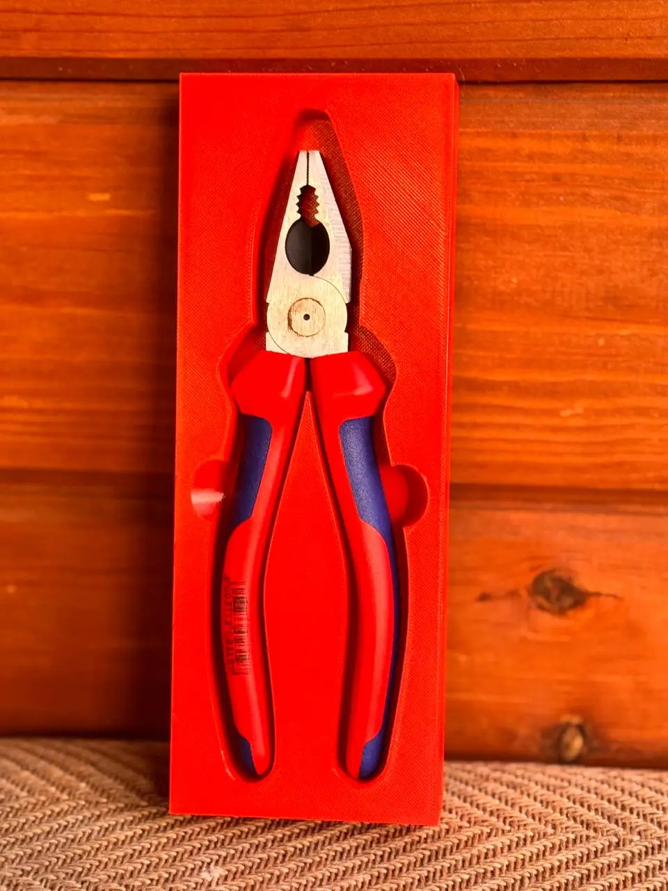
Enter the drawer's internal width and length, arrange wrenches, screwdrivers, pliers, sockets and measuring tools, then print a fitted tray for the workstation.
Custom tool case insert
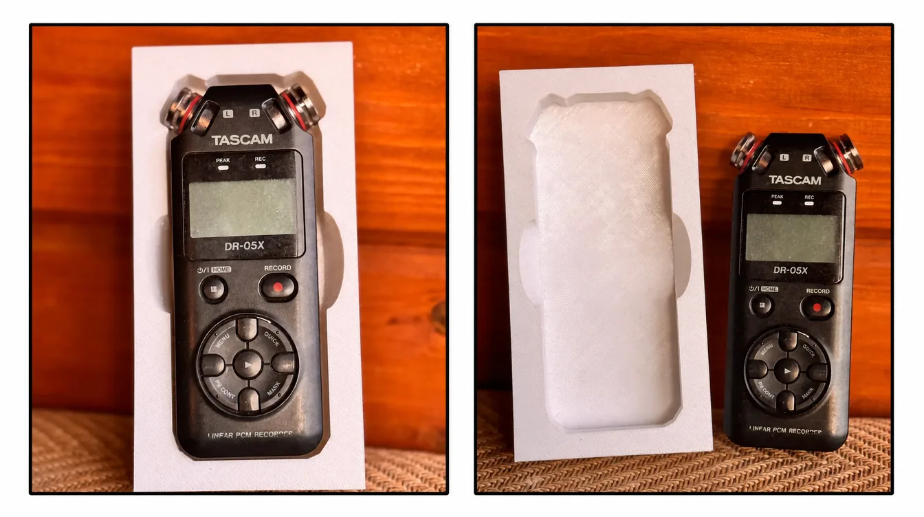
The workflow suits instruments, cameras, audio gear, controllers and accessories with a clear top silhouette. Objects with complex side geometry require a particularly careful fit check.
Product box or packaging insert
Build an insert to the internal dimensions of a box and arrange a product or component set inside it. The generator creates insert geometry; it does not calculate impact protection, material properties or shipping loads.
Workshop and production organizer
A saved model can be reused for matching workstations, service kits or small production runs.
Gridfinity module
For modular storage on a 42 mm grid, use the dedicated Gridfinity Generator. It creates a base in whole cells and lets you set height, pocket depth, a stacking lip and magnet holes. Gridfinity exports are available as STL and 3MF.
When the generator can replace CAD—and when it cannot
The AIPRINTGEN generator is a good fit when the pocket shape is defined by the object's top projection and a constant pocket depth is sufficient.
It is especially useful for:
- flat or relatively even tools;
- drawer organizers;
- standard case inserts;
- packaging inserts;
- fast fit prototypes;
- repeatable parts.
Additional CAD work may be necessary for:
- multiple depth levels within one pocket;
- undercuts or side retainers;
- clips, latches or locks;
- a fit based on the object's lower 3D surface;
- cable channels;
- multi-part assemblies;
- splitting a large plate into printable sections;
- special mounts or mechanical features.
What to check before 3D printing
Scale
Compare at least one model dimension with the physical object, especially when you calibrated the image manually with two points.
Clearance and fit
Make sure the chosen clearance reflects the accuracy of your equipment. Print a test pocket first if the fit is important.
Pocket depth
The object does not have to sit fully below the plate surface. Leaving part of it exposed often makes it easier to remove.
Finger notches
Check that each notch is accessible and does not interfere with an adjacent pocket.
Bottom and pocket spacing
Check the material under each pocket and in the webs between them. Very thin sections may deform or fail during printing or use.
Machine work area
Compare the model dimensions with your printer's build area or your machine's work envelope. The generator can create a plate up to 1200 mm per side, but it does not split the plate automatically for a specific machine.
Hidden object features
Account for side buttons, connectors, projections, covers and anything else that is not visible from above. Increase clearance or edit the model when necessary.
Build cost and saved models
The first build for an uploaded photo uses 1 credit. For that same photo, you then have 5 rebuilds at no additional credit cost to refine settings or pocket positions.
The completed model is saved automatically under My Models. Access to the generator depends on an active plan that includes the tool.
Frequently asked questions
Can I make one insert for several tools?
Yes. Arrange the objects on the same level without overlaps. After detection, you can move, edit or delete each pocket separately.
Do the objects have to be photographed on an A4 sheet?
No. A4 is only a known scale reference. You can instead mark two points on any measured segment and enter the distance in millimeters.
Can I make a tool insert without CAD skills?
Yes, for a basic insert based on the top outline. Scale, depth, clearance, plate dimensions and pocket positions are set in the browser. Non-standard engineering features may still require CAD.
Does the generator create a full 3D model of the tool?
No. It uses the visible top outline to create a pocket with the depth you specify. Hidden, side and underside geometry is not reconstructed.
Which clearance should I choose?
The available values are 0.4, 0.8 and 1.2 mm. A smaller value gives a tighter nominal fit. The right choice depends on the object, material and machine calibration, so use a test pocket for a critical fit.
Can I enter an exact size for a drawer, case or box?
Yes. In the layout editor, enable the fixed blank size and enter the plate width and length in millimeters.
How large can the custom insert be?
The maximum plate side in the generator is 1200 mm. Whether it can be made in one piece depends on your machine's work area.
Which file should I download for a 3D printer?
Use 3MF or STL. The interface marks 3MF as recommended, while STL offers compatibility with most slicers.
Can I export files for laser cutting or routing?
Yes. DXF and SVG are available for a free-size insert. After export, prepare the outlines for the chosen material and equipment.
Can I order the insert already 3D printed?
The generator creates a digital model. You can print it yourself or send it to a manufacturing service. AIPRINTGEN also provides a separate 3D-printing and model-finishing service.
Start with one simple tool
A wrench, ruler, caliper, pair of pliers or screwdriver makes a good first project. Photograph it directly from above and verify the scale before building the model.
 Our community


