How to Prepare a Bas-Relief STL from a Photo for CNC

Preparing a relief for CNC starts with usable source geometry. The AIPRINTGEN bas-relief generator turns a photo, drawing or logo into a 3D relief on a flat base; this guide explains how to compare versions, check the controls and move the STL into CAM.
An STL is three-dimensional geometry, a height map is a greyscale representation of relative height, and G-code is a set of commands for a specific machine; they are not interchangeable. The generator does not calculate G-code: scale, stock, tooling, strategies, post-processing and simulation belong in CAM.
CNC preparation at a glance
- Input: a photograph, drawing, sketch or logo.
- Output: a watertight STL bas-relief model on a flat base.
- Several versions are available after generation: compare them on the same source and choose the suitable geometry.
- Post-generation controls: 2–120 mm height, Detail, Sink into base, Contour smoothness, lower-plateau cut and surface smoothing.
- Special modes: negative mould and mirroring.
- A rebuild after parameter changes uses the already computed relief and does not start a new AI generation.
What the bas-relief generator is good for
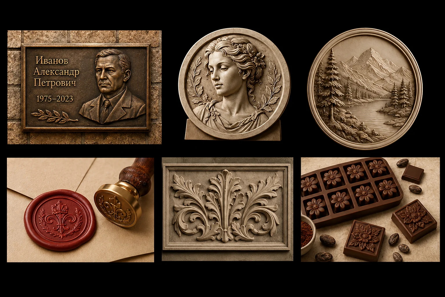
A bas-relief translates a flat image into physical volume while keeping the compact form of a plaque or a decorative overlay. For CNC, the most useful projects are those where you need the source geometry quickly and then refine the process in your usual CAM system.
- a portrait for CNC, a commemorative plaque or a memorial plate;
- a bas-relief from a photo of a person, a pet, a car or an object;
- a logo, coat of arms, monogram, maker's mark or signage element;
- an icon, decorative panel, furniture ornament or architectural detail;
- a belt buckle, souvenir, token or decorative insert;
- a negative mould for plaster, resin, soap, candles, chocolate and ceramic impressions;
- a mirrored stamp, seal or embossing die.
The same STL bas-relief can be scaled and adapted for CNC milling, 3D printing or the making of a master model. The specific material, tooling and machining parameters are chosen later, at the production stage.
If you need not a plaque but a full model you can look at from every side, follow the step-by-step guide to creating a 3D model from a photograph.
STL model, height map and G-code: the difference
People searching for "CNC height map" usually mean a greyscale image where pixel brightness sets the relative height of the surface. AIPRINTGEN produces a different kind of result — a watertight 3D bas-relief model in STL on a flat base. For the maker that is the source geometry, which then has to be opened in CAM and turned into toolpaths.
| Result | What it is | Its role in production |
|---|---|---|
| STL model | Three-dimensional polygon geometry of the piece. | Import into CAM, a slicer or a 3D editor; scaling and production preparation. |
| Height map | A raster image where shades encode height. | Used in certain relief and engraving processes, if the specific software supports them. |
| G-code | Movement and operation commands for the machine. | Produced after toolpaths, tooling, machining parameters and the post-processor are set in CAM. |
An STL bas-relief model is therefore not a finished machining program. If you are used to building bas-reliefs in ArtCAM, Aspire or another CAM environment, the generator can shorten the manual construction of the initial volume; scale, stock, cutters, strategies and the post-processor are still configured in your own workflow.
How to make a bas-relief from a photo: step by step
Let us walk through the workflow using a belt buckle as the example. The source photograph has a clearly readable central subject, a pronounced silhouette and decorative details — a suitable basis for a 3D bas-relief from a photo.

Step 1. Prepare a suitable image
The quality of the source directly shapes the future relief. The algorithm reads contours, light, shadows and visible transitions as cues to depth, so a clean reference almost always yields a more predictable 3D model for CNC.
- at least 300 pixels on the longer side; 1000 pixels or more is recommended for fine detail;
- a sharp subject without heavy digital noise or blur;
- good separation of the subject from the background;
- soft lighting without harsh shadows hiding important details;
- an angle that matches the intended composition;
- sufficiently large features: small text and thin lines must survive at the real size of the piece.
A practical tip for CNC. Do not judge the image on screen alone. If a letter, a vein or a contour on the finished piece ends up narrower than your finishing cutter, that detail will not be reproduced no matter how good the STL is. First decide the size of the piece and the tooling available, then choose the level of detail.
What to do when the source reads poorly
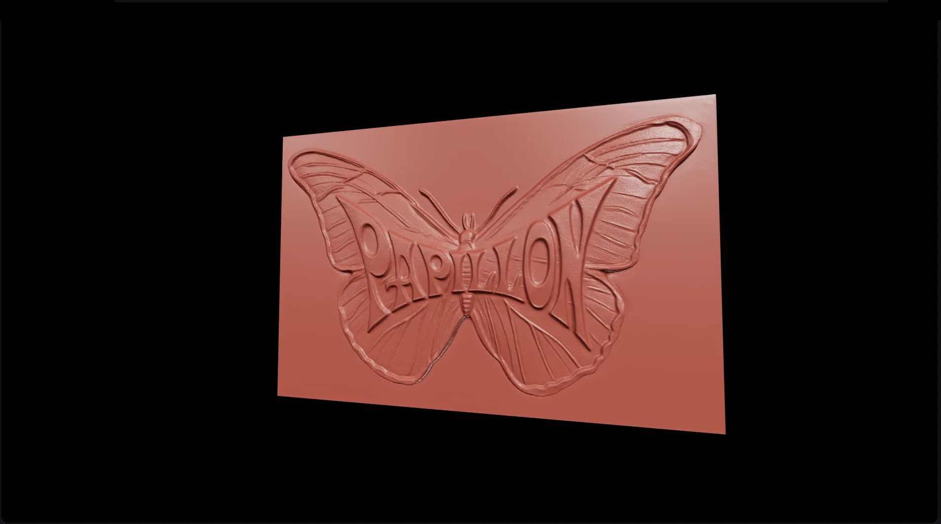
An old photo of the Papillon logo shows a typical problem. The mark occupies a small part of the frame, is distorted by perspective and carries almost no light-and-shadow cues about real volume. Simple cropping and comparison of the available versions produced a shallow, lifeless relief.
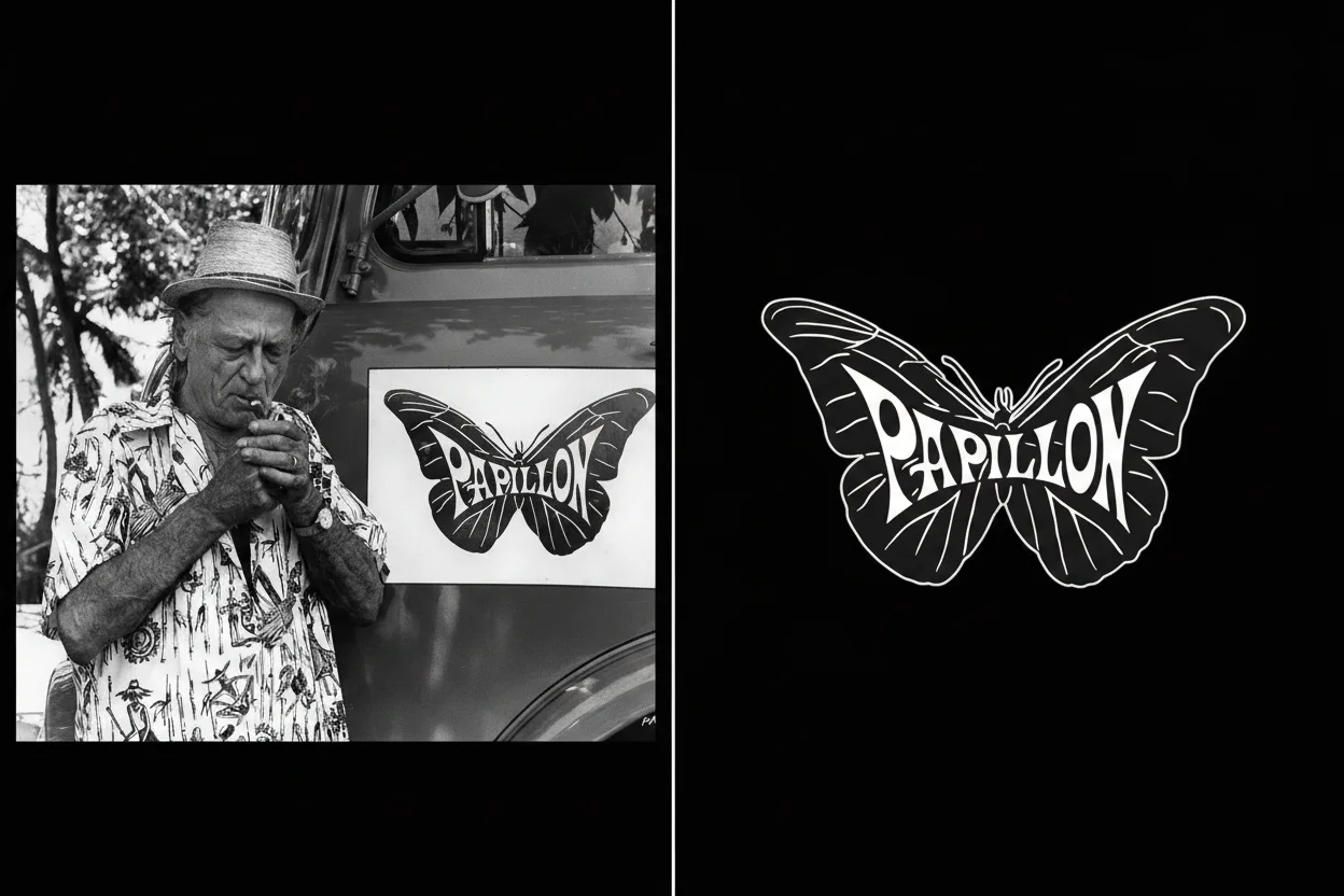
The result improved once the reference had been prepared in the UltraGen tab: the logo was separated from the background, its resolution increased and it was presented as a volumetric metal object with clear facets and material. The main takeaway: the generator reconstructs the volume that can be read in the image. If depth is not visually expressed, improve the reference first. More on removing backgrounds, increasing detail and changing the angle in the article "UltraGen in AIPRINTGEN".

Step 2. Compare the available versions
After generation, the service shows several versions produced by the currently available methods. Their number and character may change, so compare the results on the same source once processing is complete.
| Criterion | Softer-volume example | Stronger-contour example |
|---|---|---|
| Suitable source | A photograph, a realistic object, a portrait. | A drawing, a sketch, line art, a logo. |
| Character of the relief | Smooth reconstruction of large forms, a classic bas-relief. | A more contrasted and sculptural height pattern. |
| Strength | Natural transitions and coherent volume. | Good readability of lines and elements where volume is not stated directly. |
| Possible risk | Fine graphics may soften. | Noise, shadows and background may turn into roughness or stray geometry. |
Do not choose by a fixed method number in advance. Compare large-form continuity, contour readability and noise, then continue with the version that best fits the source and the intended job.
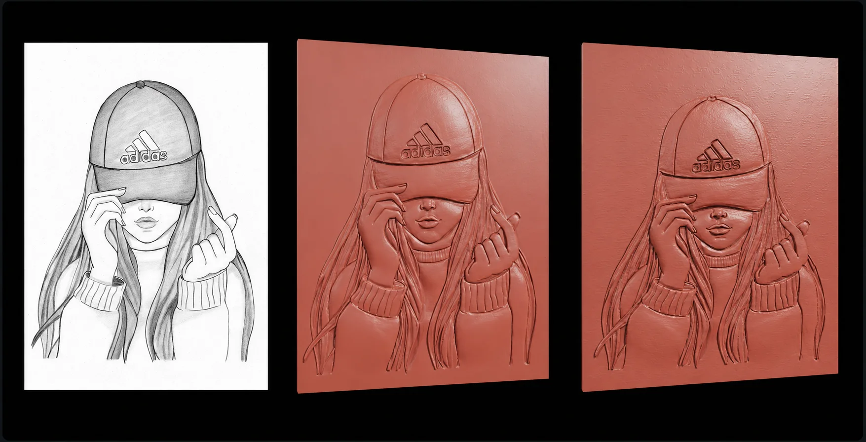
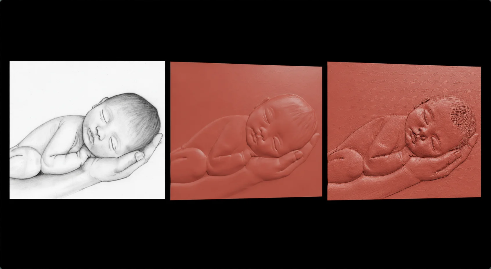
Step 3. Create the first model
After generation, the version with the more coherent volume was selected for the buckle photograph. Rotate the model in the built-in viewer and inspect it from the front, side and oblique angles.
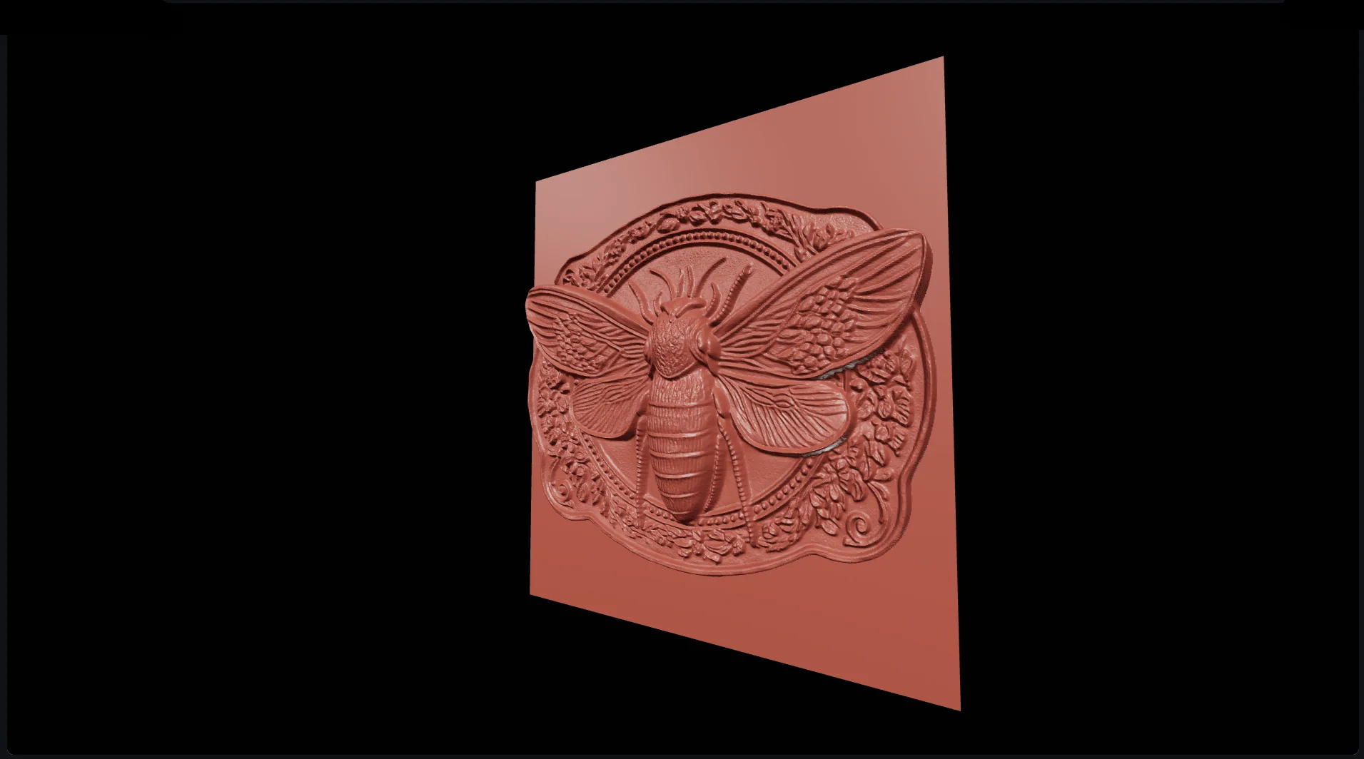
The Adjust relief panel includes height, Detail, Sink into base, Contour smoothness, lower-plateau cut and surface smoothing. Detail may emphasise noise and cannot restore information absent from the source; Sink lowers and clips the form but is neither base thickness nor lower-plateau cut; Contour smoothness affects only the outline-crop silhouette, not the relief surface. Rebuild uses the already computed relief and does not start a new AI generation.
Step 4. Tune the relief for production
Do not judge the settings by how impressive they look in the viewer alone. Milling cares about depth along Z, tool access to every zone, machining time and the strength of thin features; 3D printing cares about layer height, orientation and minimum thickness; moulds care about draft angles and whether the piece can be released.
Relief height
This parameter sets how far the image protrudes above the base and is adjustable from 2 to 120 mm. Choose it from the finished size, available stock depth and cutter reach: a deeper relief removes more material and may extend the machining cycle.
For CNC, start from the finished size. First set the physical dimensions of the piece and the depth available in the stock. Only then choose the relief height. The maximum value in the viewer is not necessarily the optimal one for milling.
Base-plateau cut
This function removes the reconstructed volume around the central subject and is adjustable from 0 to 50 per cent. It helps when the background of the image has ended up in the geometry and you want a cleaner plaque or want to bring out the main motif. At a high value the surface approaches a flat base.

Smoothing
Smoothing reduces small irregularities and calms the transitions between depth levels. It helps remove noise and false geometry that the algorithm may have reconstructed from shadows or photographic artefacts. Too high a value, on the other hand, erases fine ornament, facial features and small lettering.

Edge feathering
This parameter controls the transition between the subject and the plane of the base. A soft edge often looks more natural on a portrait; for a logo, coat of arms, geometric ornament or maker's mark, a crisper contour is usually more useful. Increase the value gradually and check that the silhouette stays readable at the real scale.
Negative moulds and mirrored stamps
The generator can prepare more than a raised relief: it also produces special geometry for casting, embossing and transferring an image.
Inversion: the mould instead of the finished piece
The "Recesses" mode turns protruding areas into cavities and vice versa. That gives you a negative model for plaster, resin, decorative soap, candles, chocolate or a ceramic impression.
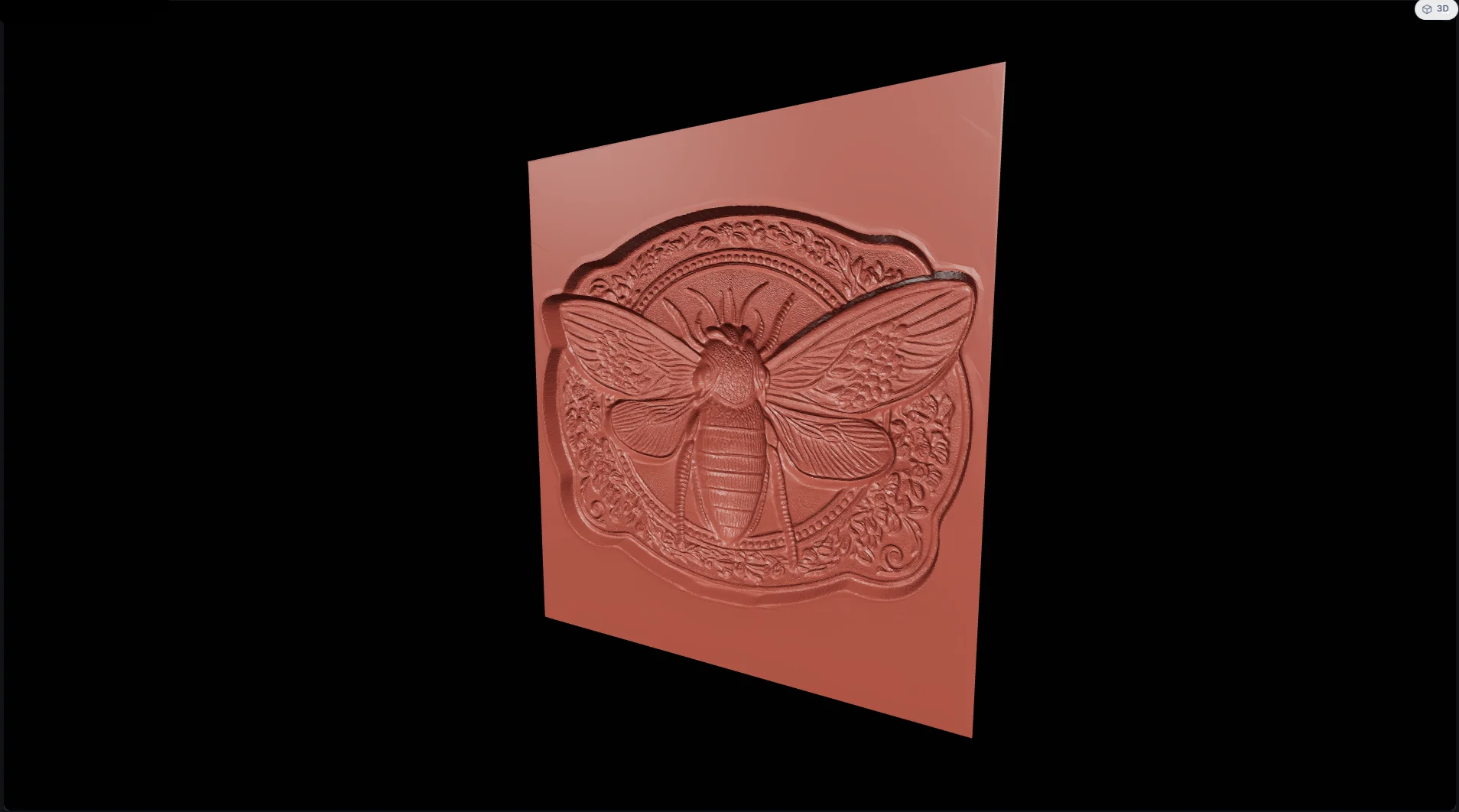

After inversion the model must be checked against the process: the depth of the mould, minimum wall thickness, draft angles, material shrinkage and whether the finished piece can be released.
Mirroring: a correct impression
For stamps, seals, maker's marks and embossing, the image on the tool has to be mirrored so that text and artwork read correctly after transfer. This function matters especially for monograms, logos and lettering.

Step 5. Save the STL and hand the model to CAM
After a parameter change, the model is rebuilt from the already computed relief data without a new AI generation. The selected version is saved in My models, and the STL can then be downloaded for the next production stage.
The generator creates a watertight model on a flat base, but the final scale and process parameters must be checked against your specific machine, material and tooling. That matters especially for CNC: a handsome 3D relief in the viewer is no guarantee that every detail is reachable by the cutter you have chosen.
How to prepare an STL bas-relief for CNC milling
To turn a bas-relief for milling into a working program, import the STL into CAM and check the geometry and the process step by step. This stage stays on the maker's side.
- Set the final dimensions along X, Y and Z and check the units after import.
- Decide the base thickness, the stock dimensions, the allowance and the workholding.
- Compare the smallest feature of the relief with the diameter of the finishing cutter and the stepover.
- Check the usable tool length, access to deep zones and the absence of undercuts unreachable in 3-axis machining.
- Split the work into roughing and finishing strategies; do not use a fine cutter to remove a large volume.
- Set the part zero and the model orientation; for a stamp, make sure mirroring is enabled beforehand.
- Run a toolpath simulation and check for collisions, remaining material and machining time.
- For a critical part, run a test at reduced size or in a softer material.
| Stage | What happens |
|---|---|
| The AIPRINTGEN generator | Source 3D geometry, version comparison, relief tuning, inversion, mirroring, STL export. |
| The CAM system | Scale and position, stock, tooling, strategies, machining parameters, simulation, post-processor and G-code. |
If you are looking for relief-creation software, or you are used to building bas-reliefs in ArtCAM or Aspire, the online generator is handy precisely as an accelerator for the first stage: it produces the STL bas-relief model, while your familiar CAM environment remains the place where you take the project to the machine.
Frequently asked questions
Can I create a bas-relief online without manual 3D modelling?
Yes. Upload a photograph, drawing or logo, compare the generated versions and tune the relief. The quality of the result still depends on the source: clear contours, a suitable angle and understandable light and shade give more predictable geometry.
Can I create an STL from a photo?
Yes. AIPRINTGEN builds a 3D bas-relief from a photo and lets you download a watertight STL model on a flat base. Set the final scale and check the fine details before production.
Is an STL bas-relief suitable for CNC?
Yes, as source 3D geometry for CNC. The STL has to be imported into CAM, where you set the dimensions, the stock, the cutters and the strategies, and generate the G-code for your particular machine.
Which is better for CNC: STL or a height map?
They are different formats. A height map encodes depth as raster shades; an STL contains polygon 3D geometry. The generator outputs STL. Which format you use next depends on your CAM system and your process.
Does the generator replace building a bas-relief in ArtCAM or Aspire?
It can replace or substantially shorten the manual construction of the initial volume, but it does not replace CAM preparation. Toolpaths, tooling, machining parameters and the post-processor are configured separately.
Can I make a portrait for CNC?
Yes. Use a large photograph with soft lighting, a clear face and few overlapping details. Compare the available versions and choose the one where the face and large forms read most cleanly.
Can I get a mould or a stamp?
Yes. Inversion creates the negative geometry of a mould, and mirror mode prepares the correct image for a seal, maker's mark or embossing die. Draft angles, thicknesses and release must be checked separately.
From image to finished relief
AIPRINTGEN produces source STL geometry from a flat image. After generation, compare the versions and adjust 2–120 mm height, Detail, Sink, Contour, lower-plateau cut, surface smoothing, inversion and mirroring; rebuilding those parameters does not start a new AI generation.
For a CNC maker this is a shorter route from a photograph or a logo to the source geometry. After export, what remains is professional CAM preparation: set the scale, choose the tooling, calculate the toolpaths and verify the machining in simulation.
Other AIPRINTGEN tools
The ecosystem offers further tools for other 3D-printing scenarios:
Riggable: how to turn a 3D model into an articulated figure →
Custom insert generator: cases, boxes and inserts from a photo →
 Our community


